Email: sales1@yzconn.com Tel: +86-21-64128668
- All
- Product Name
- Product Keyword
- Product Model
- Product Summary
- Product Description
- Multi Field Search

Views: 0 Author: Site Editor Publish Time: 2026-07-22 Origin: Site


Choosing a wire to board connector often looks simple until pitch, current, wire size, mounting direction, and retention start competing for the same space. A connector that fits the PCB may still overheat, strain the solder joints, or complicate assembly if the full cable-to-board path is not considered. Modern connector ranges span compact pitches, multiple circuit counts, crimp or IDC terminations, and different locking options, making selection increasingly application-specific.
Understanding how these parts work together helps engineers compare designs, confirm operating limits, and prevent failures before production.
The electrical path begins where the conductor meets its terminal. In a crimped design, conductor strands are compressed into the terminal while a second area supports the insulation. In an IDC design, a slotted contact cuts through the insulation and bears against the conductor. The terminal locks into the housing, mates with the PCB header, and transfers current through the solder joint to the board trace. Any weak point in the wire to board connector can raise resistance, interrupt a signal, or reduce retention.
Mechanical features keep the interface stable. Terminal locks prevent contact back-out, polarization and keying reduce incorrect insertion, latches resist separation, and strain relief limits cable force at the contact. Power circuits demand thermal control, while low-level signals need stable resistance and interference control. Mixed-signal housings work when pin assignments separate noisy power from sensitive signals and provide suitable return paths.
A detachable wire-to-board connector is usually preferred when the PCB and harness are built separately, tested at different stages, or replaced independently. It supports repeatable mating and avoids soldering near finished wiring during repair. Board-in termination reduces the number of components, while direct soldering may suit products that will never be disconnected.
Every separable contact adds resistance, dimensional tolerances, and another controlled assembly step. Designers should not add a wire to board connector when there is no manufacturing or maintenance need. The choice should follow service life, board space, production method, and the consequences of an intermittent connection.
Pitch is the center-to-center distance between contacts and affects more than connector width. A compact wire to board connector with a finer pitch can save PCB area, but it may narrow the compatible wire range, reduce electrical spacing, and make handling or inspection harder. Circuit count should follow the electrical architecture, with spare positions added only for defined needs. The chosen terminal must also accept the conductor size, strand construction, insulation diameter, and strip length.
Wire and connector dimensions require joint evaluation. A housing may fit the board yet fail if the cable cannot bend or the terminal cannot support the conductor. YZCONN offers wire-to-board configurations that vary by pin count, row arrangement, pitch, pin shape, material, and electrical level. These options should be evaluated only after the load, space, wire, and assembly constraints are defined.
SMT mounting preserves through-hole space and suits automation, but its joints must tolerate mating and cable forces. Through-hole mounting generally provides stronger anchoring, although it consumes plated holes and can restrict routing. Vertical, right-angle, top-entry, and side-entry formats change cable routing, clearance, and insertion direction.
Before releasing the PCB, check mated height, footprint, latch access, cable bend radius, keep-out area, and withdrawal path. The harness should not press against an enclosure edge or force the wire to board connector sideways after assembly. Serviceable products need latch access without requiring technicians to pull on the wires. Enclosure features, tie points, or a defined harness route can prevent solder joints from becoming the only mechanical support.
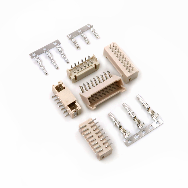
The YZCONN PH-series wafer provides a useful example of how connector specifications affect PCB integration. Its 2.0 mm pitch, SMT mounting, 2–20-position configuration range, and high-temperature housing suit compact layouts and reflow assembly. It functions as the PCB-side element of a complete wire to board connector system.
Design approval still requires verified values for current, voltage, compatible terminals, wire range, plating, retention, durability, footprint, and reflow conditions. The table below connects these checks to practical risks.
Design requirement | Specification to confirm | Typical trade-off | Risk prevented |
Limited PCB area | Pitch, positions, and mated dimensions | Size versus handling access | Layout conflict or blocked latch |
Required load | Current, temperature rise, and wire range | Density versus thermal margin | Overheating or voltage drop |
Automated assembly | Packaging, coplanarity, and reflow profile | Speed versus process control | Placement or solder defects |
Cable retention | Latch, terminal lock, and strain relief | Service access versus retention | Terminal back-out or separation |
The catalogue rating for a wire to board connector is a starting point, not a guarantee for every finished assembly. Usable current changes with resistance, wire size, loaded positions, bundling, PCB copper, airflow, duty cycle, and enclosure temperature. Heat can accumulate below the nominal current limit, so the full connection should be treated as one thermal path.
The weakest element sets the operating limit. A large contact cannot compensate for undersized wire or protect a narrow PCB trace. Continuous current differs from a short peak because the assembly must eventually reach thermal equilibrium. Derating should therefore reflect the intended environment and be supported by temperature-rise testing with the expected number of loaded contacts.

Testing should use the production wire, terminal, housing, board, and enclosure rather than an isolated connector sample. Temperature should be measured near the contact, wire entry, solder joint, and PCB interface. Safe current capacity depends on the complete wire to board connector assembly and correct termination, not the housing alone.
Current mainly drives heating, while voltage determines insulation stress between conductive parts. Working voltage must be evaluated alongside clearance, creepage, contamination, humidity, altitude, and insulation performance. Fine pitch may suit a low-voltage design but fail an application requiring wider electrical separation.
Signal circuits raise different questions. Low-level measurements need stable contact resistance, while faster signal edges make pin assignment, return paths, crosstalk, cable geometry, and shielding more important. Ground contacts may need to flank sensitive lines, and power conductors may require separation from analog or communication circuits. A fine-pitch, high-pin-count wire to board connector should not be assumed to support high-speed data without appropriate electrical validation.
Crimp termination creates electrical contact and mechanical support without heating the wire, but repeatability depends on the approved terminal, compatible conductor, strip length, crimp height, applicator, and maintained tooling. Pull-force checks can identify major faults, but they do not replace crimp-height control or cross-section analysis.
IDC termination can remove stripping and insertion steps in suitable high-volume production. Successful termination still depends on conductor construction, insulation dimensions, slot geometry, and insertion depth. Neither method is automatically less expensive after tooling, inspection, scrap, rework, and field failures are considered. The termination method should match the actual wire to board connector, harness design, production volume, and service requirements.
Retention must match the mechanical environment. Friction retention may work inside a protected enclosure, while positive latching better resists cable pull, transport, vibration, and service handling. Secondary locks reduce terminal back-out risk but add assembly and inspection steps. Strain relief remains necessary because a strong latch cannot prevent repeated cable flexing from loading the terminal.
Temperature cycling, humidity, dust, chemicals, and corrosion can change contact behavior over time. Plating should be selected according to signal level, environmental exposure, mating frequency, contact force, and cost. Mating-life requirements also differ between a connector opened once during factory testing and one disconnected during routine maintenance. Electrical, thermal, mechanical, and environmental tests should reflect the conditions the finished product will experience.
Many wire to board connector failures begin with process deviations. Intermittent signals may result from incomplete mating, terminal back-out, contamination, weak crimps, or cracked solder joints. Overheating can trace to excessive current, poor derating, high resistance, undersized wire, or inadequate PCB copper. Wire pull-out usually indicates incorrect crimp dimensions, incompatible insulation, poor terminal seating, or missing strain relief.
Wrong-circuit connections have different causes. Similar housings can be cross-mated when polarization, labeling, or assembly sequencing is weak. A damaged latch may appear seated while providing little retention, and poor SMT coplanarity can create uneven joints that initially pass a continuity check. Production controls should cover terminal seating, crimp dimensions, pull force, latch condition, coplanarity, and solder quality.
Acceptance criteria must be measurable. A fully inserted terminal should correspond to a defined visible or gauged position, while crimp quality should follow approved settings and inspection limits. Cable-handling instructions should specify the permitted pull direction, bend radius, and insertion method. Stable production depends on controlling the process rather than relying only on final inspection.
Validation should examine the assembled wire to board connector rather than treating the connector, wire, and PCB as unrelated approved parts. The plan can scale with product risk, but it should reproduce the electrical, mechanical, and environmental conditions expected in use.
● Inspect dimensions, terminal seating, mating fit, pin mapping, and continuity before stress testing.
● Measure contact resistance and temperature rise at realistic load, ambient temperature, and energized-contact count.
● Verify crimp cross-sections or pull force, connector retention, and mating life where disconnection is expected.
● Apply vibration, shock, humidity, or thermal cycling when the operating environment requires it.
Environmental or mechanical exposure should be followed by repeat electrical measurements. A connector may remain attached while contact resistance becomes unstable, and a harness may pass room-temperature continuity but fail after thermal expansion or vibration. Testing before and after exposure helps reveal changes that a visual inspection cannot detect.
After validation, the approved terminal, housing, wire, PCB footprint, tooling, and process settings should be locked into controlled documentation. A visually similar terminal or a different strand construction can change crimp performance even when the housing still mates. Inspection limits, test conditions, and revision status should remain connected to the bill of materials and work instructions. This discipline turns a wire to board connector from a catalogue item into a repeatable production interconnect.
Choosing a wire to board connector should begin with the complete application: electrical load, wire size, PCB space, cable routing, environmental exposure, termination method, and service requirements. Confirming these factors together helps prevent overheating, unstable contact, assembly errors, and unnecessary redesign.
Yz-Link Technology Co., Ltd. provides wire-to-board connector options and customized wire-harness support for projects with different pitch, circuit-count, mounting, and integration needs. Matching the connector and harness to verified operating conditions can simplify production, improve maintenance, and create a more reliable cable-to-board connection.
A: A wire to board connector creates a removable connection between wires or cable assemblies and a PCB, allowing power or signals to transfer between circuits.
A: Selection depends on current requirements, pitch, pin count, wire size, mounting method, environmental conditions, and the required locking or termination style.
A: Wire-to-board connectors connect a cable or wire harness to a PCB, while wire-to-wire connectors join two separate wire assemblies without a circuit board interface.
A: Reliability depends on contact quality, proper termination, current loading, mechanical retention, temperature conditions, vibration resistance, and correct assembly processes.
A: Yes. SMT wire to board connectors can save board space and support automated assembly, but footprint design, solder quality, and mechanical stress must be carefully considered.
A: Common methods include crimp termination and insulation displacement connection (IDC). The suitable option depends on wire type, production volume, assembly requirements, and service needs.


