Email: sales1@yzconn.com Tel: +86-21-64128668
- All
- Product Name
- Product Keyword
- Product Model
- Product Summary
- Product Description
- Multi Field Search

Views: 0 Author: Site Editor Publish Time: 2026-07-01 Origin: Site


Choosing an RF Cable often seems straightforward until signal loss, impedance mismatch, limited routing space, or the wrong connector begins affecting performance. A cable that works well for a short internal connection may be unsuitable for a longer run, higher frequency, or demanding installation environment.
A reliable choice depends on matching the complete signal path—not simply selecting the lowest-loss option. By considering frequency range, impedance, cable length, power, flexibility, shielding, and connector compatibility together, you can narrow the options and select an assembly that delivers stable performance without unnecessary cost or complexity.
Define the lowest and highest frequencies that must pass through the link. Testing, harmonics, additional radios, or future channels may extend the requirement beyond a device’s headline band. The RF cable, connectors, and any unavoidable adapter must support that complete range because the lowest-rated component limits the assembly.
Impedance belongs in the same decision. Most wireless RF systems use 50 ohms, while many video distribution systems use 75 ohms; mixing them can reflect energy. The selected RF cable should match the source, load, connectors, and intermediate components. Relevant selection criteria also include frequency range, shielding method, voltage withstand, connector type, and signal loss.
Evaluate attenuation within the system link budget. Start with the maximum tolerable loss, subtract connector and adapter losses, and allocate the remainder to the cable run. Compare each RF cable at the actual frequency and finished length because loss rises with both.
Diameter shapes the trade-off. Larger conductors generally reduce resistive loss and can support more power, but they add stiffness and weight. Smaller constructions fit compact equipment yet often impose more loss per unit length. Convert published attenuation values to the planned length and retain margin for production and installation variation.
The shortest practical route is usually preferable, but pulling an RF cable tight across a chassis or forcing a sharp corner can alter the geometry that maintains impedance. Leave enough length for the specified bend radius, strain relief, connector access, and service.
A receive path places different demands on an RF cable than a transmitter output. For higher-power or pulsed systems, check continuous power, peak power, voltage, temperature, and load mismatch. A raw coax rating may not apply to the finished assembly if a connector or termination becomes the limiting element.
Return loss and VSWR indicate how closely the path is matched. Reflected energy reduces delivered power and may increase local heating, so low attenuation cannot offset incorrect impedance or poor mating. Use enough operating margin for temperature shifts, manufacturing tolerance, and imperfect loads without over-specifying every category.
Application question | Information to define | Specification to check |
Which signals must pass? | Lowest and highest operating frequency | Rated frequency range |
How much loss is acceptable? | Link budget and finished length | Insertion loss or attenuation |
Is this a transmit path? | Continuous and peak power | Power and voltage ratings |
What impedance is required? | Source and load impedance | 50Ω or 75Ω compatibility |
Electrical performance can eliminate a candidate, but mechanical reality determines whether it will survive. Measure routing space, connector clearance, panel position, and the tightest unavoidable turn before choosing the cable diameter. A thicker RF cable may reduce loss and carry more power, yet its bend radius and stiffness can make it impractical inside a compact enclosure.
Movement must be described accurately. A static jumper only needs to tolerate installation, whereas a test lead, hinged assembly, or moving antenna may experience repeated flexing. Dynamic use shifts the priority toward flexible conductor and shield structures, smooth strain relief, and controlled bend zones. Pulling force, vibration, crushing, and torsion also matter because many failures begin near the cable-to-connector transition.
Bend radius is not just a packaging number. Repeatedly bending an RF cable below its rated limit can disturb the shield, deform the dielectric, and change impedance over time. Phase stability may also matter in measurement, timing, or multi-channel systems where small electrical-length changes affect results. No construction maximizes every attribute, so minimum loss, tiny diameter, long flex life, high power, and low cost must be ranked rather than assumed to coexist.
Shielding should correspond to the noise environment. Foil can provide broad coverage, braid supports mechanical strength and low-resistance grounding, and combined structures can improve isolation near transmitters, motors, switching supplies, or dense wiring. Additional layers may also make an RF cable thicker and less flexible, so they should solve a defined interference problem.
The jacket protects the assembly from temperature, moisture, UV, oils, fuels, cleaning chemicals, and abrasion. Specify those exposures before selecting the material rather than assuming an indoor construction will survive outdoors. Grounding and shield termination also deserve attention because a well-shielded RF cable can still perform poorly when the shield connection is incomplete or mechanically unstable. A compact RF Cable with an SMA-to-U.FL configuration can use silver-plated copper braid, an FEP jacket, and an operating range of -40°C to +85°C, illustrating how shielding and environmental limits belong beside the electrical specifications.
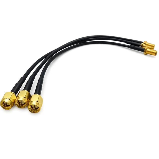
Connector selection begins with the actual ports. Record the series at both ends, male or female configuration, standard or reverse polarity, straight or right-angle orientation, and whether the interface is cable-mounted, bulkhead-mounted, or attached to a PCB module. Panel thickness, nut access, mating clearance, and exit direction can determine whether an otherwise suitable RF cable fits the enclosure.
Physical mating does not prove electrical compatibility. Two parts may connect while having the wrong impedance, unsuitable frequency rating, incorrect polarity, or inadequate power capacity. Adapters can solve occasional interface problems, but each added junction introduces loss, mismatch risk, extra length, and another failure point. A direct connector combination is usually better for a repeatable production design.
The termination must be designed for the selected cable diameter, conductor, dielectric, and shield structure. A poor transition can disturb impedance even when the separate connector and coax specifications appear suitable. Contact alignment, shield bonding, attachment method, and strain relief all affect the stability of the completed RF cable.
Repeated mating creates a different wear mechanism from repeated cable flexing. A connector can reach its practical cycle limit while the coax remains intact, or the termination can fail because users rotate the cable body instead of the coupling nut. Frequent-change applications should therefore specify connector durability and handling procedures separately from flex-life requirements.
Raw-cable attenuation does not describe every completed length and termination. Confirm whether frequency range, insertion loss, VSWR, power handling, temperature rating, and dimensional tolerances apply to the coax alone, one connector, a standard sample, or the exact RF cable being purchased. The strongest evidence is measured performance for a representative finished assembly at the required length and frequencies. For a critical link, request the test method and reference-plane definition as well, since connector losses can be included or excluded depending on how the measurement is set up.
A compact YZCONN SMA-female-to-U.FL pigtail provides a useful example. It uses 1.13 mm coax, a 50-ohm controlled-impedance path, an SMA female bulkhead interface, and a small U.FL connector for the internal radio side. Its operating range extends from DC to 6 GHz, its maximum VSWR is 1.5 across that range, and its finished length can be customized.
That combination can suit short connections between an external antenna port and a PCB-mounted wireless module in a constrained enclosure. It should not automatically be chosen for a long outdoor feed or high-power transmitter, where attenuation, weather sealing, power capacity, and mechanical protection may dominate. Product data becomes useful only after every value is mapped to the intended signal path.
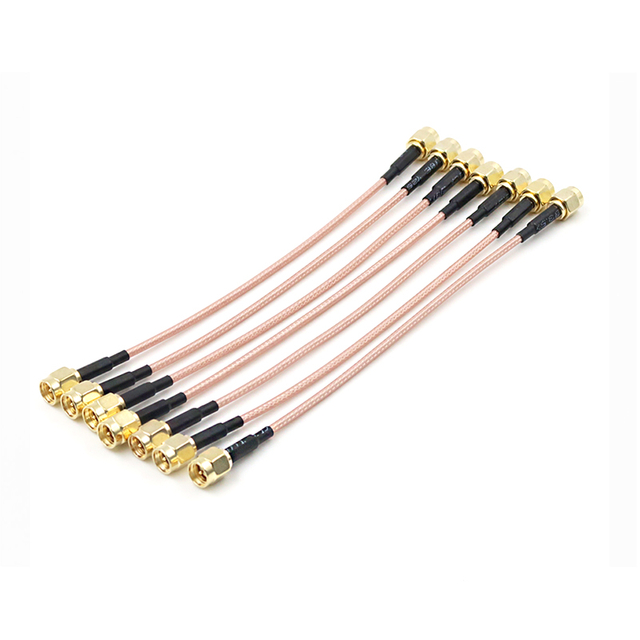
Build a pass-or-fail list before comparing prices. Correct impedance, full frequency coverage, acceptable loss, suitable power capacity, correct connectors, environmental resistance, and routing compliance are normally mandatory. Any RF cable that fails one of them should leave the shortlist.
Rank secondary preferences such as weight, flexibility, shielding, delivery, and service life. Total installed cost should include adapters, hardware, labor, rework, downtime, and replacement risk rather than only unit price.
A simple scorecard keeps the decision transparent. Rate each compliant RF cable against the same weighted criteria, then record the supporting test values or specifications. This prevents an attractive price or one exceptional specification from outweighing several weaker but more consequential results.
A standard RF cable assembly works when its length, connector pairing, orientation, frequency range, loss, power rating, and environmental limits already meet the application. Customization is justified for an exact length, mixed connector pair, panel hardware, controlled exit direction, specialized jacket, labeling, or added strain relief.
Length deserves special care. Excess cable adds loss and routing loops, while a short assembly loads the terminations. The SMA-to-U.FL pigtail can be customized in common lengths such as 50, 100, 150, and 200 mm to suit different enclosure layouts.
Document the measurement method, connector orientation, labeling, packaging, and acceptance criteria. Clear drawings reduce ambiguity before production.
Verify each shortlisted RF cable with samples when the design is compact, custom, or high-volume. Check panel fit, mating access, routing, bend radius, strain relief, and nearby-component clearance. Critical applications should also measure continuity, insertion loss, and return loss or VSWR across the band.
Installation quality can change the result. Damaged contacts, contamination, over-torque, sharp bends, crushing, and cable-body rotation can create discontinuities. Proper cleaning, alignment, and specified coupling torque help preserve the match.
Record a baseline so later changes in loss or match can be compared with the original measurement.
Selection criterion | Candidate A | Candidate B | Candidate C |
Covers the complete frequency band | Pass/Fail | Pass/Fail | Pass/Fail |
Loss at the required length | Value | Value | Value |
Correct connectors and orientation | Pass/Fail | Pass/Fail | Pass/Fail |
Fits routing and bend limits | Pass/Fail | Pass/Fail | Pass/Fail |
Handles the operating environment | Pass/Fail | Pass/Fail | Pass/Fail |
Requires customization | None/Minor/Major | None/Minor/Major | None/Minor/Major |
Selecting the right RF Cable comes down to matching electrical performance with the realities of the installation. Frequency range, impedance, signal loss, power handling, connector compatibility, bend radius, and environmental exposure should be evaluated as one system rather than as separate specifications. Yz-Link Technology Co., Ltd. offers standard and customized RF cable assemblies that can help engineers achieve suitable lengths, connector combinations, and routing configurations for specific equipment. A clearly defined requirement sheet, supported by sample testing where needed, makes procurement more efficient and reduces the risk of costly installation changes.
A: Match the cable’s frequency range, impedance, attenuation, power handling, connector type, bend radius, shielding, and environmental rating to the complete signal path.
A: Use 50 ohms for most radio, wireless, and test systems, while 75 ohms is common in video and broadcast applications. Match all connected components.
A: Longer cables introduce more attenuation, especially at higher frequencies. Keep the run as short as practical while allowing enough length for safe routing and strain relief.
A: Yes. Connectors must support the required frequency, impedance, and power level. Poorly matched or unnecessary connector transitions can increase insertion loss, reflections, and mechanical failure risk.
A: Not necessarily. A lower-loss cable may be thicker, heavier, or less flexible. The better choice balances electrical performance with routing space, movement, durability, and cost.


