Email: sales1@yzconn.com Tel: +86-21-64128668
- All
- Product Name
- Product Keyword
- Product Model
- Product Summary
- Product Description
- Multi Field Search

Views: 0 Author: Site Editor Publish Time: 2026-07-29 Origin: Site


Choosing a connector is rarely as simple as matching two housings. Pitch, wire size, current load, PCB space, locking method, and assembly volume can all change which option is suitable—even when several parts look nearly identical.
A wire to board connector may use crimp terminals, insulation displacement, direct-wire clamps, or a power-focused housing-and-header system. Understanding how these types differ helps engineers and buyers avoid compatibility problems, poor crimps, overheating, and unnecessary assembly cost. Comparing their construction and use cases makes it easier to choose a connection that fits the circuit, enclosure, production process, and expected service conditions.
A crimp wire-to-board connector system consists of three coordinated parts. A stamped terminal is crimped onto the stripped conductor, snaps into an insulating housing, and mates with a vertical or right-angle PCB header. This modular construction lets manufacturers prepare a cable harness away from the board and install it during final assembly. It suits appliances, control boards, lighting products, sensors, and other low-to-medium-power equipment.
Retention may rely on friction, polarization, or a positive latch. Polarized features block reversed mating, while a latch helps resist vibration and accidental cable movement. The wire-to-board connector must be evaluated as a complete system because a strong housing cannot compensate for a loose terminal or poor crimp. Conductor compression, insulation support, terminal retention, and mating contact force all contribute to reliability.
Pitch is the center-to-center spacing between adjacent contacts, influencing width, electrical spacing, wire range, and handling. A smaller pitch saves PCB area and supports higher density, but tiny terminals are harder to position, crimp, and inspect. Medium-pitch systems generally leave more room for larger conductors, stronger housing walls, and easier manual assembly. The right choice depends on both enclosure space and cable requirements.
Similar-looking housings should not be assumed to mate correctly. Two wire-to-board connector families may share a nominal pitch while using different terminal shapes, keying, latch geometry, insertion depth, or header dimensions. A vertical header directs the cable away from the PCB, whereas a right-angle header routes it parallel to the board. Compatibility should be confirmed from a complete dimensional drawing rather than photographs alone.
Customization becomes useful when the PCB footprint, enclosure, or harness architecture cannot change. Variables include circuit count, row layout, pin length, pitch, header orientation, housing shape, cable length, wire color, and end preparation. A custom Wire to Board Connector can also arrive as part of a completed harness, reducing separate sourcing and inspection.
YZCONN provides OEM and ODM socket, pin-header, connector, and cable-assembly configurations based on drawings or physical samples. Available services can include custom design, mold development, flexible production volumes, wire processing, and electrical testing. These capabilities are relevant when a standard assembly cannot satisfy a fixed interface or when the connector and harness must be supplied as one validated unit. Customization should solve a measurable constraint rather than add unnecessary variation.
An IDC wire-to-board connector forces an unstripped conductor into a slotted metal contact. The slot cuts through the insulation and grips the conductor, eliminating separate stripping and individual terminal crimping. This process suits ribbon cable because several conductors remain in a fixed order and can be terminated in one controlled operation. It can reduce labor and wiring errors when identical assemblies are produced repeatedly.
IDC is less flexible when conductors must separate or follow different routes. Cable pitch, conductor size, insulation type, contact count, orientation, and strain relief must match the selected system. Tooling needs to apply even pressure so every contact reaches the intended depth. For a wire-to-board connector used in volume production, IDC works best when repeatability matters more than free wire routing.
PCB terminal blocks connect stripped conductors directly to a board-mounted component. Screw clamps are adjustable, spring clamps maintain contact force without relying on screw torque, and push-in versions accept solid or ferrule-terminated wires quickly. Lever-operated designs can simplify releasing fine-stranded conductors. These methods suit controls, power supplies, building systems, and equipment serviced on site.
Direct-wire options usually occupy more space than a compact wire-to-board connector, but they remove the need for a matching cable housing and terminal-crimping process. Selection should account for conductor type, field access, expected rewiring, and installer skill. A guarded entry and clear circuit marking can reduce stray strands and wiring mistakes.
Connector type | Wire preparation | Best suited for | Main selection concern |
Crimp housing and header | Strip and crimp | Discrete wires and harnesses | Terminal and tooling compatibility |
IDC connector | Usually no stripping | Ribbon cable and repeated assembly | Cable spacing and termination pressure |
PCB terminal block | Strip or fit a ferrule | Field wiring and service access | Current rating and board footprint |
A power wire-to-board connector is selected around current, voltage, contact resistance, and acceptable temperature rise rather than size alone. Power designs usually use larger terminals, wider spacing, thicker housing features, and stronger retention. Those features help carry load and resist forces from heavier cables, but they do not create an unlimited safety margin.
Electrical ratings apply under defined test conditions, so a large connector may still be unsuitable for the real circuit. Ambient temperature, conductor size, PCB copper, contact loading, and the number of energized positions can alter thermal performance. Voltage requirements also depend on spacing, insulation, contamination, and operating environment. Selection should use conditions that closely resemble the intended installation.
The wire, crimp terminal, mating contact, PCB header, solder joint, and board trace form one current path. A bottleneck increases resistance and may cause localized heating even when the housing appears undamaged. Undersized conductors are risky, but a poorly compressed crimp can be equally serious because fewer strands carry current effectively. The terminal must match conductor cross-section and insulation diameter.
Review the permitted wire range, current per contact, simultaneous loading, ambient temperature, and PCB trace capacity. Derating may be needed when several power contacts operate together or the connector sits near hot components. Cable routing matters because a sharp bend can transfer force to the terminal. A power wire-to-board connector should be evaluated inside the actual enclosure when thermal margin is limited.
Crimping is generally preferable to adding solder to a contact designed for compression. A controlled crimp provides both an electrical joint and strain support, while solder can create a stiff transition in the conductor. In production, crimping should be treated as a controlled process supported by suitable tooling, repeatable settings, and inspection criteria.
Positive locks, secondary retention, polarization, and strain relief address different failures. The latch keeps the plug mated, secondary retention limits terminal backout, polarization reduces incorrect assembly, and strain relief limits cable load on individual contacts. These features are valuable in vibrating equipment, frequently serviced products, or assemblies with heavy wires.
Installers need clearance to operate the latch and should disconnect by pulling the housing rather than the conductors. Sealing may be appropriate where moisture, dust, or contamination can reach the interface, although it is an environmental requirement rather than a separate category. The selected wire-to-board connector must remain secure under forces expected in the finished product.
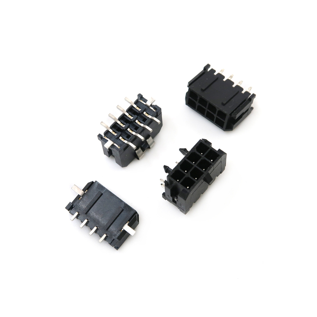
Begin with non-negotiable values before comparing shapes. Record maximum current, working voltage, circuit count, conductor gauge, insulation diameter, and temperature range. These figures eliminate unsuitable families and prevent designers from choosing a small housing first, then forcing the cable to fit. The wire-to-board connector must also suit expected mating cycles and finished-equipment requirements.
Signal circuits may prioritize density and routing, while power circuits demand closer attention to resistance and heat. Mixed-function systems may need separated contacts or extra spacing. Compare cost only after these constraints are satisfied.
Verify the interface with dimensional drawings and the enclosure model. Check pitch, circuit count, row arrangement, header height, mounting method, wire-entry direction, keep-out area, and latch clearance. A right-angle header may solve a height problem but require more board-edge space, while a vertical version may conflict with a lid. Through-hole mounting adds anchoring; surface-mount options suit compact automated assembly.
Technicians need room to mate and release the connector. The harness must bend without pressing against sharp edges or nearby parts. Color coding can help, but mechanical polarization is more dependable. The correct wire-to-board connector should fit both the CAD model and assembly sequence.
Termination method affects labor, tooling, quality control, and cost. Hand crimping may suit prototypes, automatic processing improves repeatability at scale, IDC works for ordered cable, and terminal blocks make sense for field wiring. Each approach moves labor and inspection to a different stage.
Connector price alone is misleading because total cost includes contacts, housings, wire preparation, tooling, setup, inspection, rework, and training. Consistent crimp quality depends on terminal positioning, conductor compression, insulation support, correct contact location, and compatible tooling.
For a production wire-to-board connector, define checks before releasing orders. Useful controls include conductor position, terminal retention, continuity, polarity, and pull-force sampling. Inspection depth should reflect electrical and service risk.
Replacement work should begin with measurement, not appearance. Measure pitch across several contacts, count circuits, and document row arrangement, latch, keying, wire-entry side, and mounting direction. Photograph the housing, header, terminal, and markings, and retain the mating half when possible.
Nominal pitch does not establish compatibility. Contacts may differ in retention position, mating depth, wire range, or crimp geometry, while housings may use different keys and latches. Mixing unrelated parts can create weak contact force or incomplete seating. Measuring pitch together with contact count and visible mechanical features provides a practical starting point for identification.
Custom sourcing is justified when the PCB footprint cannot change, no suitable mating part exists, a special feature is required, or the harness must arrive tested. Provide controlled drawings, materials, electrical limits, environmental conditions, and inspection criteria rather than only a sample. A custom wire-to-board connector succeeds when the interface is measurable and verifiable.
Selecting the right Wire to Board Connector means balancing electrical load, wire size, PCB space, termination method, and mechanical demands rather than choosing by appearance alone. Crimp systems suit flexible harnesses, IDC supports repeatable multi-wire assembly, terminal blocks simplify field wiring, and power connectors provide the contact size and retention needed for heavier loads.
When standard parts do not fit the layout or production process, Yz-Link Technology Co., Ltd. can support custom connectors and wire harness assemblies tailored to specific pin arrangements, cable lengths, and installation needs. A well-matched connection reduces assembly errors, improves serviceability, and supports more consistent product performance.
A: It connects individual wires or a cable assembly to a printed circuit board through a mating housing, terminal, header, clamp, or insulation-displacement interface.
A: Common options include crimp housing-and-header systems, IDC connectors, PCB terminal blocks, fine-pitch signal connectors, locking connectors, and larger power-focused designs.
A: Check current, voltage, wire gauge, pitch, circuit count, mounting direction, locking method, temperature range, PCB space, and the planned termination process.
A: Wire-to-board connectors terminate conductors at a PCB, while board-to-board connectors directly join two printed circuit boards without a separate wire harness.
A: IDC connectors suit ribbon cables and repetitive multi-wire assemblies because their contacts pierce the insulation, allowing several conductors to be terminated without individual stripping.
A: Measure the contact pitch, count the positions, and document the latch, keying, wire entry, PCB mounting style, markings, and mating connector.


