Email: sales1@yzconn.com Tel: +86-21-64128668
- All
- Product Name
- Product Keyword
- Product Model
- Product Summary
- Product Description
- Multi Field Search

Views: 0 Author: Site Editor Publish Time: 2026-07-15 Origin: Site


An RF cable that works well in a WiFi router may perform poorly in an aircraft, medical device, or test bench. Cable length, frequency, impedance, shielding, connector type, and installation conditions all influence how much signal reaches its destination. Longer coaxial runs generally introduce more loss, especially as frequency rises.
Understanding where RF cables are used makes selection far easier. The sections ahead examine wireless networks, industrial and automotive systems, harsh environments, healthcare equipment, and RF testing, then connect those applications to practical choices involving attenuation, routing, durability, and connector compatibility.
Routers and access points often place radio electronics in one location and the antenna in another. A short flexible RF cable or pigtail bridges that gap, allowing the antenna to sit above an obstruction, outside an enclosure, or closer to the intended coverage area. Better placement can be undermined by excessive cable length because coaxial attenuation rises with both length and frequency; tight bends can also degrade performance. The practical goal is the shortest route that reaches a useful antenna position without straining the connector.
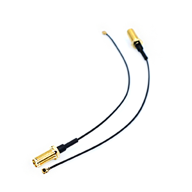
YZCONN’s RG174 SMA female WiFi antenna extension cable illustrates this compact role. Its inner conductor, dielectric, and outer shield create a flexible coaxial path for short antenna extensions rather than a long feeder run. It is most relevant when routing freedom and connector access matter more than maximum-distance transmission. That distinction keeps selection tied to the installation instead of a generic “low-loss” label.
Cellular modems, IoT gateways, and embedded radios often use a small board-level connector while the external antenna uses a larger interface. An RF cable pigtail makes that transition without placing the antenna directly on the circuit board. It also lets designers route around batteries, displays, or shielding metal and position the radiating element more effectively. Connector compatibility, bend space, strain relief, and minimum practical length are the main checks. Enclosure feedthroughs should also protect the cable from abrasion and prevent the connector from carrying mechanical load.
Radio and broadcast installations use the same electrical principle on a larger, more permanent scale. RF cables link receivers, transmitters, antennas, distribution hardware, and monitoring equipment, so impedance and shielding must remain consistent across every junction. These RF cable routes may pass through racks, walls, or outdoor transitions where sealing, support, and inspection access affect reliability. The complete path—including adapters and terminations—should be treated as one transmission line. Planned inspection access makes later fault isolation faster and less disruptive.
Factories place wireless sensors and telemetry modules near motors, drives, switching supplies, relays, and heavy power cabling. Such equipment creates electromagnetic noise that can contaminate a weak radio signal before it reaches the receiver. A shielded RF cable provides a controlled path between the antenna and communication module, while secure termination limits intermittent behavior caused by vibration or handling. Routing should also avoid sharp edges, moving mechanisms, hot surfaces, and long parallel runs beside high-current conductors.
Selection should follow the machine layout rather than a vague demand for “industrial grade.” A fixed sensor inside a sealed cabinet may prioritize compact diameter and shielding, whereas a movable head may need repeated-flex capability and strain relief. Connector retention matters when technicians routinely open panels or replace modules. These choices control signal-path variability without requiring an oversized assembly. They also make replacement predictable because cable movement and connector access have been considered before the machine enters service.
Vehicles use RF interconnects for GPS antennas, cellular modems, infotainment receivers, and telematics units. The antenna and electronic module are often mounted in different areas, making RF cable routing part of the system design. Narrow channels, clips, trim panels, vibration, and temperature cycling all place mechanical demands on the connection. Short, supported runs with secure mating interfaces are preferable to loose coils of excess cable.
A right-angle connector may prevent an immediate sharp bend behind a module, while a straight connector may be easier to inspect where depth is available. The correct orientation preserves bend radius and connector engagement after final assembly. It should also leave enough service access for replacement without disturbing nearby wiring. Mounting clips should support the cable without crushing its coaxial geometry.
Aircraft communication, navigation, and radar systems need RF cable assemblies that remain stable through vibration, altitude changes, and wide temperature ranges. Restricted space and weight limits make “more shielding” or “larger cable” incomplete answers because each improvement brings a mechanical or mass trade-off. Designers evaluate impedance, frequency, attenuation, shielding, connector retention, and bend radius as one requirement. Coaxial cable families can differ substantially in impedance, shielding, frequency rating, temperature range, and connector compatibility.
Installation discipline is equally important. A compliant RF cable can still underperform if it is kinked, unsupported near a connector, or repeatedly disturbed during maintenance. Secure clamping, controlled bends, and accessible inspection points help preserve measured performance. These practices matter most where diagnosing a degraded link in service is difficult. Documented routing and connector identification also reduce mistakes during inspection or module replacement.
Satellites and remote antenna systems add a severe constraint: access after deployment may be limited or impossible. Low attenuation protects the signal budget, while shielding reduces coupling between densely packed subsystems. Weight remains a competing concern, so shielding effectiveness and spacecraft mass must be balanced rather than evaluated separately.
The RF cable assembly should be evaluated in its installed geometry, not only as a straight bench sample. Flexing, thermal movement, and connector loading can alter the electrical path over time. Mission details differ, but the practical rule is consistent: define the exposure, verify the construction, and avoid unqualified substitutions after testing. Remote terrestrial sites benefit from the same discipline because weather and limited access magnify small installation errors.
Medical systems use RF connections in imaging hardware, monitoring equipment, diagnostic instruments, and wireless devices. Clean signal transfer is only one requirement; electromagnetic compatibility with nearby equipment also matters. Medical devices must operate within their intended electromagnetic environment without causing or experiencing unacceptable interference. Wireless coexistence becomes especially important when several connected devices operate in the same clinical area.
Layout may require an RF cable to pass through a compact enclosure, tolerate repeated positioning, or support cleaning and service procedures. MRI environments demand system-specific engineering because conductive leads and coil cables can interact with radiofrequency energy and magnetic fields. Generic cable recommendations are therefore insufficient for such installations.
In laboratories and production lines, the RF cable forms part of the measurement path. It connects signal generators, spectrum analyzers, network analyzers, fixtures, antennas, and devices under test, so its loss and reflections can appear in the result. Insertion loss measures transmission loss, while return loss and VSWR describe reflection behavior associated with impedance discontinuities. These measurements evaluate different aspects of the cable path and should not be treated as interchangeable.
A short general-purpose RF cable may suit basic checks at moderate frequencies. Higher-frequency or low-level measurements may justify a characterized low-loss or phase-stable cable. The decision should follow the uncertainty budget and test method rather than price or appearance.
Measurement accuracy depends on repeatability as well as nominal specifications. Worn interfaces, contamination, sharp bends, and changing cable position can alter insertion loss or reflection between tests. An RF cable may look intact while its electrical behavior has shifted, so periodic insertion-loss checks can help identify a worn or damaged signal path.
Inspect mating surfaces, support the cable, and avoid flexing it at the connector. Replace assemblies that produce unstable readings instead of compensating indefinitely in software. When phase consistency matters, characterize the cable in the same routed position used for measurement.
Selection should begin with the signal, not the connector catalog. Identify the operating frequency, confirm system impedance, estimate the practical cable length, and determine how much insertion loss the link budget or measurement uncertainty can accept. A compact assembly that works between two boards may introduce excessive attenuation when extended to an external antenna, especially at higher frequencies. Cable diameter, dielectric, conductor construction, and shielding can then be balanced against flexibility and environmental needs.
Impedance must remain consistent through the cable, connectors, and connected equipment. A mismatch reflects part of the signal instead of delivering it to the load; return loss and VSWR are common ways to evaluate that behavior. Length is also a specification because coaxial runs should remain as short as practical to limit unnecessary attenuation.
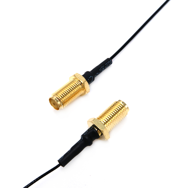
After defining electrical requirements, verify the physical interface at both ends. Specify connector family, plug or jack, standard or reverse polarity where applicable, straight or right-angle orientation, mounting style, and retention needs. Miniature interfaces suit crowded enclosures, while threaded connectors can improve retention in exposed locations. Each adapter adds another junction and maintenance point.
YZCONN’s RG316 pigtail range demonstrates how one flexible 50-ohm cable format can support N, TNC, BNC, UHF, MCX, MMCX, TS9, and CRC9 interfaces in straight or right-angle arrangements. The range is useful only after the mating equipment and polarity have been verified; similar-looking connector names are not automatically interchangeable.
Application | Primary Cable Priority | Typical Installation Concern |
WiFi antenna extension | Flexible, short signal path | Antenna placement |
Industrial telemetry | Shielding and secure routing | Electrical interference |
Vehicle connectivity | Compact, vibration-resistant connection | Tight installation space |
Aerospace communication | Controlled loss and mechanical reliability | Harsh operating conditions |
RF measurement | Stable, repeatable performance | Measurement accuracy |
A complete brief should specify length, routing space, bend radius, exposure, and expected movement. It should state whether the assembly remains fixed, moves occasionally, or flexes repeatedly. These details prevent a common error: choosing the correct connector and impedance but the wrong mechanical construction. The best RF cable assembly is the one that still meets its electrical target after installation.
Choosing the right RF cable starts with the application rather than a single specification. Wireless networks, industrial equipment, vehicles, aerospace systems, medical devices, and test instruments each place different demands on signal loss, shielding, flexibility, connector type, and mechanical reliability. Matching those factors helps protect signal integrity while avoiding unnecessary cost or installation complexity.
Yz-Link Technology Co., Ltd. provides RF cable assemblies and connector configurations for varied equipment layouts, including RG174 and RG316 options. These solutions can help engineers simplify routing, improve interface compatibility, and build connections suited to the system’s actual operating conditions.
A: An RF cable carries high-frequency signals between antennas, transmitters, receivers, wireless modules, and test instruments in communication, automotive, industrial, medical, aerospace, and measurement systems.
A: Most RF cables use coaxial construction, but the terms are not identical. “Coaxial” describes the cable structure, while “RF” describes its high-frequency signal application.
A: A 50-ohm cable is common in radio, WiFi, and test systems, while 75-ohm cable is typically used for television, video, and broadcast distribution.
A: Yes. Signal loss increases with cable length and usually becomes greater at higher frequencies, making short routes and suitable low-loss cable important for longer connections.
A: Match the cable’s impedance and frequency rating to the equipment, then evaluate attenuation, length, power handling, shielding, bend radius, connectors, and environmental exposure.


