Email: sales1@yzconn.com Tel: +86-21-64128668
- All
- Product Name
- Product Keyword
- Product Model
- Product Summary
- Product Description
- Multi Field Search

Views: 0 Author: Site Editor Publish Time: 2026-07-08 Origin: Site


An RF cable can meet its datasheet values and still underperform once installed. Impedance mismatches, unnecessary length, tight bends, weak shielding transitions, or connector stress can increase loss and reflections or create failures that appear only after vibration and repeated handling.
Reliable RF cable assembly design therefore depends on more than choosing a familiar coaxial cable and matching connectors. Engineers need to balance frequency, impedance, attenuation, routing space, mechanical load, environmental exposure, and production testing as one system. The following sections show how to turn those requirements into an assembly that performs consistently from prototype through volume production.
Identify whether the system requires 50Ω or 75Ω operation before selecting the RF cable, connectors, adapters, or test fixtures. The source, transmission line, and load should use the same impedance standard. When one section differs, part of the signal is reflected, which can degrade return loss, raise VSWR, reduce delivered power, and lower receiver sensitivity.
A connector that physically mates is not automatically electrically compatible. Similar-looking connector families may use different internal geometries or impedance ratings, so visual compatibility should never replace specification review.
Many two-way wireless and antenna systems use 50Ω interfaces, while video, broadcast, and broadband paths commonly use 75Ω. These patterns offer a useful starting point, but the equipment specification remains the controlling reference. Record the impedance at every interface instead of assuming the cable type defines the entire system.
Adapters and test equipment must follow the same rule. A correctly selected cable can still produce poor results when connected through a mismatched adapter, bulkhead fitting, splitter, or measurement fixture. Reviewing the complete signal path early is much easier than diagnosing reflections after the hardware has been assembled.
Define the operating frequency range, required cable length, signal power, maximum insertion loss, and acceptable return-loss or VSWR limits. RF cable attenuation generally rises with frequency and length, so a generic low-loss description is not enough for design approval. Performance must be evaluated at the actual operating frequencies.
The total loss budget should include more than the cable itself. Both connector terminations, adapters, bulkhead transitions, switches, and other inline components contribute to the final result. Manufacturing tolerance and expected operating temperature may also influence performance.
Wideband systems need limits across the complete frequency range rather than at one convenient spot frequency. An assembly that performs well at the center frequency may exceed the loss or reflection limit near the edge of the band.
Shortening the assembly usually reduces attenuation, but the shortest possible cable is not always the best design. A cable that barely reaches its destination may create tension, force an excessive bend, or place side load on the connector. The correct length is the shortest option that still supports safe routing, assembly access, strain relief, and normal manufacturing variation.
RF cable selection should balance impedance, attenuation, outside diameter, flexibility, shielding, jacket material, temperature range, and termination practicality. No single RG family is suitable for every application, and the smallest cable is not automatically the most reliable option.
Cable family | Typical impedance | Routing profile | Main advantage | Primary trade-off |
RG178 | 50Ω | Very compact and flexible | Fits short internal runs | Higher loss and greater handling sensitivity |
RG58 | 50Ω | Medium diameter and flexible | Balanced general-purpose RF performance | Requires more space than micro-coax |
RG59 | 75Ω | Medium routing profile | Suitable for shorter 75Ω signal paths | Incompatible with 50Ω systems |
RG6 | 75Ω | Larger and relatively stiff | Lower loss on longer 75Ω runs | Needs more installation space |
RG178 works well in compact enclosures when its attenuation and bend limits fit the design. RG58 supports many general 50Ω interconnects, while RG59 and RG6 address different 75Ω routing and loss requirements. Cable length, operating frequency, enclosure space, and expected handling should determine the final choice.
YZCONN provides customizable RG178 and RG58, RG59, and RG6 assemblies with options for connector type, cable length, shielding, impedance, labeling, overmolding, and other OEM or ODM requirements. These options are useful when standard assemblies cannot meet the required routing, interface, or production configuration.
Before approving a cable family, confirm the conductor, dielectric, shielding, and jacket construction. A prototype review is especially valuable when the assembly must pass through a crowded enclosure, tolerate repeated movement, or connect interfaces with different orientations.
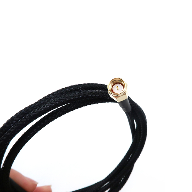
Connector selection begins with impedance and frequency capability, but physical conditions are equally important. Available space, orientation, mating cycles, retention method, environmental sealing, torque, and expected mechanical load all influence reliability.
A compact snap-on PCB connector may be appropriate for an internal transition, while an externally accessible antenna port generally needs a stronger enclosure-mounted interface. The most suitable connector is the one that matches both the operating band and the way the product will be assembled, handled, and serviced.
Connector geometry also affects routing. A right-angle termination can reduce enclosure height, but it fixes the cable exit direction and must be clocked correctly. Threaded interfaces provide strong retention, while miniature snap-on styles require accurate alignment and protection from side load.
External handling deserves particular attention. Antenna installation, repeated mating, cable pulling, or excessive tightening can transfer force into a small PCB receptacle and its solder joints. Over time, this stress may crack solder, lift pads, loosen the connector, or create an intermittent connection that is difficult to reproduce during testing.
A more reliable architecture places a bulkhead connector at the enclosure and uses a short internal coaxial jumper to reach the board. The enclosure then carries torque and tensile load, while the PCB connection carries the RF signal. This arrangement also makes the external interface easier to inspect and replace.
Finished cable length should follow the actual three-dimensional route rather than a straight-line measurement between endpoints. Include connector body length, right-angle orientation, minimum bend radius, installation access, strain-relief zones, and manufacturing tolerance.
A cable that is too short can preload the terminations, pull a miniature connector sideways, or make enclosure assembly difficult. A cable that is too long creates coils, pinch points, sharp turns, and inconsistent placement between units. Excess slack may also contact moving parts or become trapped between enclosure sections.
Route the RF cable with broad, controlled bends. Keep it away from screws, sharp edges, hot surfaces, enclosure seams, and mechanisms that can crush or rub the jacket. Avoid twisting the cable to correct connector orientation after termination. The required clocking or exit direction should be specified on the drawing.
Retention clips and localized strain relief can prevent unwanted movement, but they should not flatten the cable or force a bend directly at the connector exit. The assembly must remain secure while still allowing normal installation and maintenance movement.
A practical enclosure path is:
● PCB connector
● Short coaxial jumper
● Anchored bulkhead connector
● External antenna or cable
Bulkhead hardware stops user-applied torque at the enclosure wall, while the jumper isolates the PCB from repeated mating forces. This layout is particularly useful when the antenna can be handled, the product experiences vibration, or technicians regularly reconnect the interface. The electrical path may reach the PCB, but the external mechanical load should not.
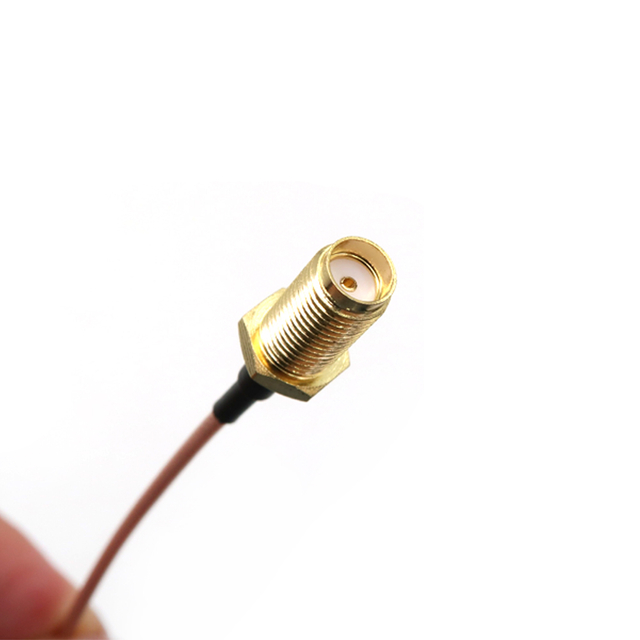
Continuity testing verifies the intended conductive path, while insulation checks help identify shorts, damaged dielectric material, or incorrect termination. These basic tests are useful, but they do not confirm high-frequency performance.
Insertion loss measures how much signal the completed assembly removes across the operating band. Return loss and VSWR indicate how strongly impedance discontinuities reflect energy. A calibrated vector network analyzer is commonly used for swept measurements across the required frequency range.
Test the finished RF cable assembly rather than relying only on individual cable and connector specifications. Termination quality, connector geometry, cable length, bend condition, and assembly workmanship all affect the measured result.
Define the calibration planes at the assembly interfaces. Adapters, fixtures, and test leads should be controlled so their performance is not mistaken for cable loss or mismatch. The same measurement setup should be used for qualification, production testing, and incoming inspection whenever practical.
For vibration-prone or flexing applications, repeat critical measurements with the assembly positioned as installed. Gently move the cable within its permitted range while observing the result. This approach can expose intermittent shield contact, a cracked conductor, a loose crimp, or a connector that changes impedance under side load.
Mechanical stress during testing should remain within the specified bend and movement limits. The purpose is to simulate service conditions, not to damage the sample intentionally. Acceptance criteria should define whether the measured values must remain stable during movement.
A production drawing should define the cable construction, impedance, finished length, tolerance, connector interface, gender, orientation, clocking, strip dimensions, termination method, strain relief, labeling, and environmental requirements.
Avoid descriptions such as standard connector, typical cable, or approximately 300 mm. These phrases allow different builds to be treated as equivalent even when they produce different electrical or mechanical results.
Where plating, jacket material, shield coverage, overmolding, or connector orientation affects performance, state it explicitly. Photographs or controlled reference samples may support the drawing, but they should not replace measurable requirements.
Acceptance criteria should include continuity, insulation where applicable, insertion loss, return loss or VSWR, workmanship, finished dimensions, visual condition, and any required environmental or flex testing. Give the frequency range and numerical limit for each RF measurement instead of requesting a generic test report.
Review a controlled prototype or first article for fit, routing, mating access, and measured performance before volume production. The sample should use production-representative materials, tooling, and termination methods.
Document approved samples, measurement setups, revision levels, and handling instructions so production and incoming inspection evaluate the same design. Changes to the cable, connector geometry, tooling, materials, or finished length should trigger review because each can alter RF behavior.
Reliable RF cable assembly design comes down to matching impedance, frequency, loss limits, connector behavior, routing, and environmental demands before production begins. Testing the completed assembly under realistic conditions helps expose reflections, intermittent connections, and mechanical weaknesses that component datasheets may not reveal.
When a standard configuration cannot meet the required length, interface, shielding, or installation constraints, Yz-Link Technology Co., Ltd. can provide customized RF cable assemblies with selectable connectors, impedance options, labeling, and production support. A clearly defined specification and validated sample can reduce rework and improve consistency from prototype through volume manufacturing.
A: Match the assembly’s impedance, frequency range, insertion-loss limit, connector interface, required length, bend radius, shielding, and environmental conditions to the complete RF system.
A: A 50-ohm cable is common in wireless and RF transmission systems, while 75-ohm cable is widely used for video and broadband. Components throughout the path must match.
A: Yes. Attenuation increases with cable length and usually rises at higher frequencies. Choose the shortest length that still allows safe routing, strain relief, and installation access.
A: Bending coax too tightly can deform its internal geometry, alter impedance, damage the shield, increase reflections, and shorten service life. Follow the cable manufacturer’s specified radius.
A: Common checks include continuity, insulation, insertion loss, return loss, and VSWR across the operating band. Flex or vibration testing may also reveal intermittent termination defects.


