Views: 0 Author: Site Editor Publish Time: 2026-06-29 Origin: Site


Engineers often face a frustrating dilemma when routing signals in compact devices. You look at a parts catalog and see two cables. They seem nearly identical. Both function as 50-ohm micro-coaxial lines. Both share an outer diameter of approximately 0.100 inches (2.5mm). They appear completely interchangeable for tight RF applications. But this superficial similarity hides critical differences.
The reality is their internal construction dictates whether your product succeeds or fails. Different jacket materials and thermal limits drastically alter assembly survival rates. They also determine long-term durability. Environmental suitability heavily depends on your final material choice. Using the wrong one can trigger catastrophic production delays or field failures.
Our goal is to provide a transparent, specification-driven comparison. We want to help engineers and procurement teams choose the right option. You will learn how to evaluate physical characteristics alongside electrical limits. By the end, you can confidently select the best cable for test environments, consumer electronics, or harsh outdoor deployments.
Thermal Tolerance: RG316 (FEP jacket) survives up to 200°C, making it highly resistant to soldering heat; RG174 (PVC jacket) caps at 85°C and requires careful thermal management during assembly.
Signal Attenuation: Both exhibit high loss at microwave frequencies due to their size, but RG316 offers marginally better high-frequency stability.
Cost vs. Application: RG174 is the economical choice for low-cost, low-power, room-temperature consumer devices. RG316 is the standard for military, aerospace, and high-durability testgear.
Assembly Dynamics: For reliable, high-yield RF coaxial cable assembly, RG316 is heavily preferred due to its dimensional stability during connector termination.
To understand how these cables perform, we must examine their raw materials. The internal architecture determines everything from flexibility to environmental survival.
The core of any coaxial cable carries the primary signal. The dielectric material separates this core from the outer shield. These two elements vary significantly between the two options.
RG174: This cable usually features a copper-clad steel (CCS) or bare copper center conductor. It relies on a solid Polyethylene (PE) dielectric. PE provides adequate electrical insulation but struggles under high thermal stress.
RG316: This standard demands a silver-plated copper-clad steel (SCCS) center conductor. Silver improves high-frequency skin effect conductivity. It surrounds this core with an extruded Polytetrafluoroethylene (PTFE) dielectric. PTFE offers extraordinary thermal resistance and dimensional stability.
The outer jacket protects the internal components from external threats. Your deployment environment dictates which material you need.
RG174 uses a Polyvinyl Chloride (PVC) jacket. PVC serves as an excellent low-cost insulator. However, it remains highly susceptible to UV degradation over long periods. Prolonged sunlight exposure turns PVC brittle. Its standard operating range sits between -40°C and +85°C.
RG316 features a Fluorinated Ethylene Propylene (FEP) jacket. Engineers often refer to this generically as Teflon. FEP delivers extreme chemical resistance. It easily repels oils, solvents, and fuels. It also provides excellent UV stability. FEP boasts a robust operating range of -55°C to +200°C. This makes it ideal for extreme industrial applications.
Both cables offer tight bend radii. They comfortably navigate cramped micro-enclosures and dense circuit boards. However, mechanical rigidity changes over time. PVC can stiffen or crack after repeated flexing in cold environments. FEP retains structural integrity much better. It survives continuous bending without compromising the internal shield.
The following table summarizes the core material specifications.
Specification | RG174 | RG316 |
|---|---|---|
Center Conductor | Bare Copper / CCS | Silver-Plated CCS |
Dielectric Material | Solid Polyethylene (PE) | Extruded PTFE |
Outer Jacket | PVC | FEP |
Temperature Range | -40°C to +85°C | -55°C to +200°C |
Shielding | Tinned Copper Braid | Silver-Plated Copper Braid |
Material differences directly influence signal integrity. Micro-coaxial cables trade low insertion loss for physical compactness. Neither option performs well over long distances.
Engineers must respect the physical limitations of small-diameter cables. Neither cable suits long signal runs at high frequencies above 3 GHz. As frequency increases, the signal travels closer to the conductor surface. This skin effect encounters higher resistance in thin wires. Both cables function primarily as short internal pigtails or bridging lines between PCBs and external antennas.
Signal attenuation measures how much power you lose over a specific distance. Because they share a similar geometry, their baseline attenuation profiles look comparable. However, material quality creates slight divergences at higher frequencies.
Here are expected decibel (dB) loss figures per 100 feet at common benchmark frequencies:
400 MHz: RG174 loses roughly 17 dB. RG316 loses roughly 16 dB.
1 GHz: RG174 loses roughly 31 dB. RG316 loses roughly 26 dB.
2.4 GHz: RG174 loses roughly 52 dB. RG316 loses roughly 44 dB.
At extended lengths, RG316 pulls ahead. However, context matters. For short Wi-Fi antenna runs under 12 inches, the measurable difference in insertion loss between the RG174 vs RG316 RF cable is largely negligible. A 10-inch run might show a difference of only 0.1 dB. This minimal gap rarely impacts system performance in consumer electronics.
Electromagnetic interference (EMI) degrades weak RF signals. Proper shielding prevents external noise from entering the line. It also stops your signal from leaking out.
RG174 uses a tinned copper braid. It provides adequate isolation for basic consumer applications. RG316 steps up to a single silver-plated copper braid. Silver offers superior surface conductivity. This enhances high-frequency shielding effectiveness. It provides better EMI/RFI isolation in electrically noisy environments. Medical devices and aerospace systems often demand this improved shielding.
Electrical theory frequently clashes with manufacturing reality. The true cost of a cable often hides on the assembly floor. Termination methods expose the starkest contrast between these two options.
Engineers consistently raise one major complaint regarding RG174. Its PE dielectric and PVC jacket melt very easily. Terminating a coaxial cable often involves soldering a center pin to the conductor. Connectors like SMA or MMCX require direct heat transfer. A hot soldering iron reaches temperatures exceeding 300°C.
When you solder an RG174 center pin, the heat travels down the copper core. The PE dielectric softens almost instantly. It swells, deforms, or melts away completely. This allows the center conductor to shift off-center. If it touches the outer braid, it creates an immediate short circuit. The PVC jacket can also shrink back, exposing the fragile braid.
Choosing RG316 solves this thermal nightmare. Its PTFE dielectric comfortably withstands standard soldering temperatures. The FEP jacket refuses to shrink back under typical iron heat. Operators can take their time to ensure a perfect solder joint. The dielectric holds the center pin firmly in place. This dimensional stability drastically improves first-pass yield rates. Manufacturers experience far fewer short circuits during mass production of any RF coaxial cable assembly.
Your manufacturing partners understand these mechanical behaviors intimately. If you consult an experienced RF connector cable supplier, they will likely raise concerns about RG174. They might quote higher labor costs to terminate it with complex micro-connectors.
Workers must use expensive heat-sinking tools. They must solder at rapid speeds to prevent melting. This specialized labor increases the assembly timeline. Higher anticipated failure rates also force suppliers to build more scrap into their quotes. Often, the increased labor cost completely offsets the initial raw material savings.
Every deployment environment presents unique mechanical and electrical threats. Matching the cable to the operational context prevents premature failures. Here are four common scenarios dictating cable selection.
Consumer Electronics & Wi-Fi Routers
RG174 remains the undisputed king of cost-sensitive electronics. Manufacturers use it extensively for standard Wi-Fi pigtails inside home routers. These devices live in climate-controlled indoor environments. They face no extreme heat or harsh chemicals. They remain stationary once deployed. Many consumer products also utilize automated crimping machines instead of hand soldering. Crimping bypasses the melting risk entirely. Under these stable conditions, RG174 delivers perfect performance at a fraction of the cost.
Testgear and Laboratory Environments
Electrical engineers treat laboratory equipment ruthlessly. Test cables get stepped on. Technicians roll chairs over them. Operators flex them continuously. They frequently brush against hot soldering irons on crowded workbenches. Testing labs strictly mandate RG316. The FEP jacket shrugs off accidental iron burns. The PTFE core survives aggressive bending. You need this extreme resilience to maintain accurate calibration during repetitive testing.
Amateur Radio (HAM) & Portable Operations (SOTA)
Amateur radio operators often deploy antennas on mountaintops. Programs like Summits on the Air (SOTA) require carrying gear in backpacks. These operators evaluate the weight-to-loss ratio carefully. They prioritize lightweight coax over ultra-low loss cables like LMR-400. RG316 provides an excellent compromise. It weighs very little. It packs down tightly into bags. Furthermore, its FEP jacket survives dragging across sharp rocks and freezing alpine temperatures.
Aerospace & Harsh Environments
Aviation and defense sectors face strict regulatory frameworks. Engineers cannot specify materials based purely on electrical specs. They must consider flammability and outgassing standards. In a vacuum, some plastics release volatile compounds. PVC is strictly forbidden in many aerospace applications. Teflon/FEP passes stringent military-spec flammability tests. It does not release toxic fumes easily. Aerospace applications necessitate RG316 by default.
Procurement teams must balance budget constraints against performance minimums. A smart sourcing strategy looks at material costs and manufacturing leverage.
A bare comparison of spool prices reveals a stark difference. RG316 carries a significant upfront cost premium. You pay for the silver plating on the conductor. You pay for the silver plating on the braided shield. You also pay for the advanced extrusion processes required for PTFE and FEP.
Conversely, RG174 represents a pure commodity. Bare copper and PVC cost very little to produce at scale. If your product moves in volumes of hundreds of thousands, this raw material delta becomes massive.
Many hardware startups struggle with internal cable manufacturing. Terminating micro-coaxial lines requires specialized tooling. Consider outsourcing your assemblies to a custom antenna cable service.
Outsourcing removes the assembly risk from your floor. You can specify exact lengths down to the millimeter. You can mix and match complex connector types. For example, you might need an RP-SMA bulkhead connector routing to a tiny U.FL connector on a PCB. A dedicated facility handles these transitions effortlessly.
Always request sweep-testing reports with your order. Professional facilities use Vector Network Analyzers (VNAs) to verify every batch. They can confirm the insertion loss and Voltage Standing Wave Ratio (VSWR). This guarantees assembly integrity regardless of which base cable you choose.
Deciding between these two micro-coaxial cables comes down to environmental stress and assembly methodology. They may look identical on the outside, but their internal chemistry dictates their ultimate value.
Choose RG174 if: You are manufacturing cost-sensitive consumer goods. Your device will operate in a climate-controlled, stationary environment. You plan to utilize crimp-style, non-solder connectors.
Choose RG316 if: You require thermal resilience for direct-pin soldering. Your product faces chemical exposure, extreme weather, or repeated flexing. You must comply with military specifications or outfit a rigorous testing laboratory.
Your next step should involve a manufacturing audit. Review your current assembly process. If operators spend too much time mitigating heat damage, upgrade your material. Consult with your manufacturing partners to evaluate heat-related termination issues before committing to a final design.
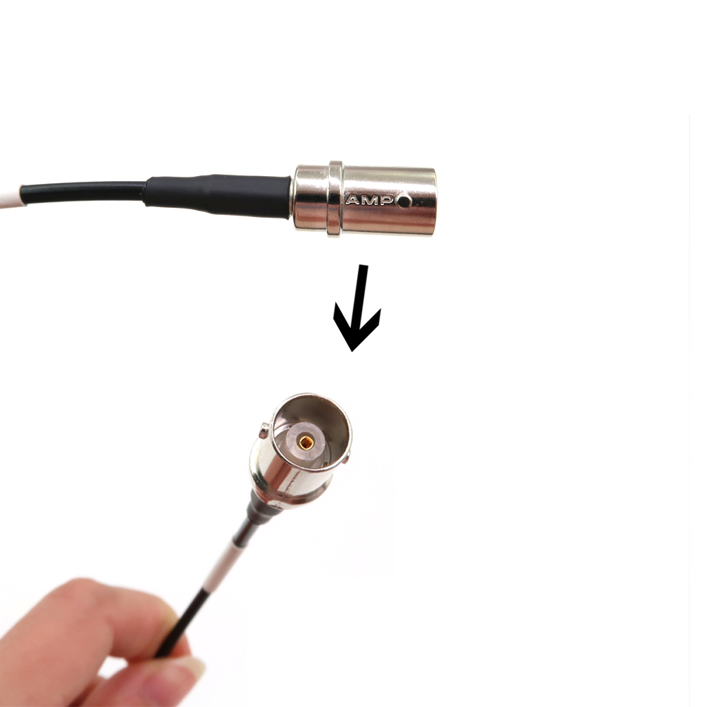
A: Yes. Because their outer diameters are nearly identical, they share the exact same connector families. You can use standard SMA, SMB, MCX, MMCX, and BNC connectors for both. However, your termination method should dictate your cable choice. If your connector requires a soldered center pin, RG316 performs significantly better.
A: Both cables suffer very high attenuation at 5GHz. For short internal pigtails under a few inches, RG316 is slightly more stable. However, if your 5GHz run exceeds four to six inches, you should consider upgrading to a lower-loss alternative. Custom micro-coax or RG178 might serve you better.
A: RG316 handles significantly higher continuous RF power. High power generates heat. The PTFE dielectric in RG316 dissipates this heat without melting. At 1 GHz, standard RG174 safely handles roughly 30 watts. At the same frequency, RG316 can handle approximately 150 watts continuously.


