Views: 0 Author: Site Editor Publish Time: 2026-06-22 Origin: Site


Choosing between SMA and IPEX connectors is never just a simple preference. It represents a critical engineering trade-off. You constantly balance mechanical robustness against valuable PCB real estate. Modern RF devices demand incredible precision. You cannot guess your way through component selection.
Selecting the wrong connector type frequently leads to disastrous field failures. Internal antennas can easily disconnect due to everyday environmental vibration. Conversely, unnecessary connector bulk can completely ruin a beautifully compact product design. These mistakes cause severe production delays. They also heavily compromise product reliability in the hands of your users. A disconnected antenna renders a smart device entirely useless.
This guide objectively evaluates both interfaces. We examine them based on harsh physical constraints. We look closely at signal integrity requirements. We also explore real-world assembly line realities. We break down these specific technical differences clearly. This detailed information helps your engineering team confidently finalize their Bill of Materials (BOM). You can move forward rapidly without ever second-guessing structural integrity.
Application divide: SMA connectors are designed for external, high-durability connections; IPEX (U.FL) connectors are engineered for permanent, space-constrained internal routing.
Lifecycle limits: A standard SMA interface safely handles 500+ mating cycles, whereas an IPEX connector degrades rapidly after 30 cycles.
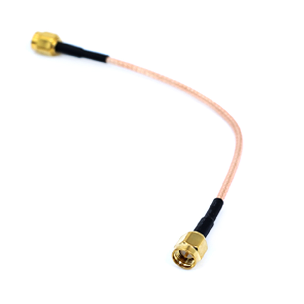
Integration reality: Most commercial IoT and radio deployments require bridging these two interfaces via a specialized adapter or pigtail.
Sourcing focus: Specifying the correct transition requires partnering with a reliable supplier who can provide tested impedance and insertion loss data.
You must evaluate modern RF design through highly specific lenses. Look closely at your available Z-axis height. Consider your target frequency bands carefully. Assess all user interaction requirements before making any final decisions. You cannot safely ignore any of these strict mechanical constraints. Signal loss ruins otherwise brilliant designs.
Designers frequently narrow down various RF cable connector types by examining physical location. Does the connection happen entirely inside a sealed enclosure? Or does it sit proudly outside facing the end-user? This simple geographical divide dictates your entire hardware strategy. Internal connections prioritize size reduction. External connections prioritize structural resilience.
Physics introduces a harsh reality into every electronics project. Larger connectors generally deliver much lower signal loss. They also handle much higher power levels safely without overheating. Meanwhile, micro-connectors sacrifice significant mechanical strength. They do this strictly to achieve extreme miniaturization. You must constantly balance high signal performance against tight packaging limits. For example, a compact drone requires extreme weight reduction. An outdoor cellular base station demands heavy-duty ruggedness. You have to align the connector choice directly to the actual product application.
The SubMiniature version A (SMA) features a highly robust threaded coupling mechanism. It provides exceptional mechanical stability under immense pressure. Precision variants operate cleanly from DC straight up to 18 GHz. Standard brass versions handle 6 GHz effortlessly. This broad operational range supports many different commercial applications. It covers everything from low-frequency telemetry up to high-band microwave communications. We highly recommend SMA hardware for heavy-duty requirements.
You will find SMA excelling in applications demanding frequent antenna changes. They are perfect for standard external test equipment connections. They also survive harsh environmental conditions effortlessly. Ruggedized industrial routers heavily rely on them. Agricultural sensors exposed to heavy wind use them extensively. If humans interact directly with the antenna, you want this threaded interface.
Building a reliable SMA RF cable assembly requires careful attention to detail. Assembly teams must use specific torque wrenches every single time. The standard required torque usually hovers around 5–8 in-lbs. You cannot skip this critical manufacturing step.
The Hand-Tightening Risk: Twisting the nut by hand creates a massive failure risk. It leads directly to completely inconsistent impedance levels. The signal will reflect backward.
The Over-Torquing Risk: Cranking the wrench aggressively is equally dangerous. It damages the delicate center pin permanently. It can also crack the internal PTFE dielectric.
Proper tooling ensures stable RF performance. We do not need to exaggerate these failure rates. The physics and standard industry tests speak clearly for themselves. You must train your assembly operators properly to avoid these common mistakes.
IPEX connectors use a brilliant micro-miniature design architecture. They feature a remarkably simple snap-on or press-fit mechanism. This delicate interface boasts an ultra-low mated height. Engineers often achieve profile clearances resting comfortably under 2.5mm. Some advanced MHF4 variants push this even lower to 1.2mm. They vanish entirely inside modern flat enclosures.
You will find IPEX inside nearly all embedded systems today. Cellular IoT modules depend on them entirely. Laptop Wi-Fi cards use them almost exclusively. Smart thermostats hide them behind sleek touch screens. They perfectly fit scenarios where the connection remains permanently untouched. You set them exactly once at the factory. You rarely touch them ever again.
These tiny connectors suffer from extreme structural fragility. Any lateral tension on the micro-coaxial cable causes major hardware problems. It easily detaches the PCB receptacle completely off the board. You must handle them incredibly gently during production routing. Pulling the wire at an angle guarantees instant failure.
High-vibration environments demand strict extra security measures. You should implement specialized post-assembly securing methods immediately. Engineers frequently apply specialized UV glue directly over the mated joint. Kapton tape offers a decent temporary fix for lighter vibrations. Non-conductive potting compounds provide excellent permanent stability. These specific mitigation strategies reliably prevent disastrous field failures.
Evaluating these two interfaces requires a direct side-by-side comparison. We must look at their specific mechanical characteristics. The table below outlines the undeniable differences between them. Use this data to justify your design choices to your engineering team.
Feature Category | Standard SMA Connector | Standard IPEX (U.FL) |
|---|---|---|
Coupling Mechanism | Threaded Nut (Requires Tool) | Snap-on / Press-fit |
Rated Mating Cycles | 500+ Operations | Approx. 30 Operations |
Typical Mated Height | 15.0 mm to 20.0 mm | 1.2 mm to 2.5 mm |
Vibration Resistance | Extremely High (When torqued) | Low (Requires supplementary glue) |
Cable Compatibility | RG174, RG316, RG58 | 1.13mm, 1.37mm, 0.81mm |
We must compare lifecycle ratings very honestly. SMA connectors comfortably endure 500 or more mating cycles. Their rugged metal threads withstand repetitive stress. Conversely, IPEX connectors degrade rapidly after roughly 30 insertion cycles. IPEX relies purely on a basic friction-fit retention method. This mechanism wears out the incredibly thin gold plating very quickly. You lose vital grounding contact over time. Frequent plugging simply destroys their intended structural integrity.
Physical thread-locking gives SMA a distinct operational advantage. It firmly resists loosening during heavy transit or sustained vibration. IPEX uses a simple snap-fit design concept. It easily pops off under minor mechanical strain. Automotive and heavy industrial use cases strictly demand threaded security. A disconnected GPS antenna in a moving delivery vehicle spells total disaster. You cannot risk intermittent data connections in mission-critical gear.
Speed matters significantly on the crowded factory floor. IPEX snap-on assembly is incredibly fast for line workers. Operators simply press them down firmly until they click. SMA installation requires much slower, precision-torqued manual steps. However, hardware rework drastically complicates IPEX usage. You absolutely must use special IPEX extraction tools to remove them safely. Pulling the wire manually is a terrible idea. It rips the delicate receptacle straight off the circuit board.
Most modern product designs require a clever hybrid workaround. You mount a sturdy bulkhead SMA connector on the exterior enclosure. You then wire it directly to an internal IPEX connector. This connection happens on the PCB via a micro-coax cable. Industry professionals commonly call this specific assembly a pigtail. Creating this highly reliable bridge means designing a custom coaxial cable solution tailored to your box.
These specific transitions often use very thin coaxial cables. Variants like 1.13mm or RG178 directly impact your overall insertion loss. Thinner cables offer excellent routing flexibility. They snake easily around tight enclosure corners and large battery packs. However, they introduce much higher signal attenuation per meter. You must rigorously account for this specific energy loss. It affects your overall RF link budget directly. Ignoring it reduces your product's maximum wireless range.
You need strict shortlisting criteria for your supply chain partners. Demand verifiable testing data entirely upfront. A truly trustworthy antenna cable assembly supplier will gladly provide accurate Network Analyzer test reports. They must show clear VSWR specifications across your required frequency bands. They also need to guarantee highly consistent crimp quality. Poor terminations cause disastrous impedance mismatches.
Follow these specific steps when evaluating your chosen manufacturing partner:
Request fully documented insertion loss charts for the exact cable length.
Verify their automated crimping equipment capabilities through factory videos or audits.
Ask for several random sample VSWR test reports from previous production batches.
Confirm their standard quality control testing metrics for solder joint integrity.
Evaluate their custom tooling inventory for delicate micro-coaxial cable types.
Solder joints must look perfectly clean under magnification. Do not accept simply assumed specifications. Verify every single electrical metric before approving the pilot run.
The final hardware decision tree remains remarkably straightforward. If the user touches the connector frequently, default to SMA. If the environment vibrates aggressively, choose SMA. If the connection lives permanently inside a compact shell, use IPEX. Both connectors serve distinctly different primary engineering purposes. First, calculate your total RF loss budget carefully. Second, physically measure your strict enclosure clearances. Finally, prepare a highly detailed custom cable drawing. Submit these precise technical requirements to your manufacturing partner today. Your product's reliability depends entirely on getting this physical layer perfectly right.
A: Not directly. You must use a specialized coaxial pigtail adapter. This specific adapter typically features an IPEX female end and an SMA female bulkhead end. It successfully bridges the micro-scale press-fit connector to the macro-scale threaded connector. This hybrid solution is extremely common in IoT devices.
A: They are designed strictly for "set-and-forget" internal manufacturing. They utilize a simple friction-based snap-fit mechanism. This delicate metal mechanism deforms slightly upon mating. Repeated plugging degrades this initial retention force rapidly. It eventually compromises the grounding contact. They sacrifice high durability to achieve extreme miniaturization.
A: No. Reverse Polarity SMA (RP-SMA) intentionally swaps the center pin and hole locations. Manufacturers do this specifically to comply with FCC regulations for consumer antennas, like home Wi-Fi routers. They are absolutely not physically compatible with standard SMA connectors without using a specific conversion adapter.


